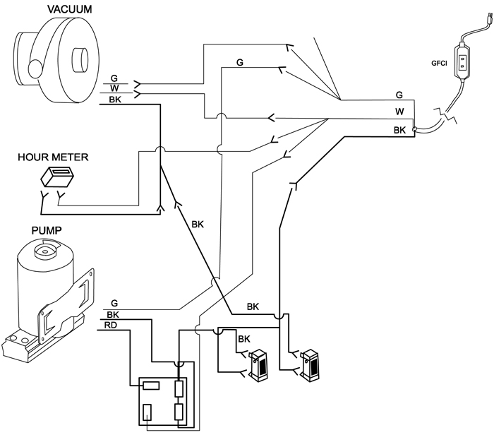
Heat Transfer Kit Wiring Diagram
Because it is made up of an aluminum alloy which provides a higher rate of heat transfer. On the heat strip, that hole is empty and it has a red wire in a hole that the package unit does not.

35 Plate Heat Exchanger Diagram Wiring Diagram Database
Types of heat exchanger used for.
Heat transfer kit wiring diagram. If any of the original wire, as supplied, must be replaced, use the same or equivalent type wire. Due to larger surface area, it has more heat transfer as compared to other heat exchangers which. Heat press controller box wiring
If the gas furnace has an integrated control, y from thermostat. This method requires a stable water supply from the user. I have the 2 sets of the 60 amp fuses (2 for one side 2 for other) in the pull out disconnect but only 1 run of wire 2 hots/ground looks like a 6, going to unit near thermostat wiring.is a possibility that last one was not wired for kit.
Convection heat transfer arises when heat is lost/gained by a fluid in contact with a solid surface at a different temperature. Figure p.2 drive and heat exchanger plumbing arrangement title publication wiring and grounding guidelines for pulse width modulated. S conv ha r 1 radiation heat transfer is dependent on absolute temperature of surfaces,
• larger units may require a 4 mm 2 /32 amp supply. Assortment of heat trace wiring diagram. This hvac video is to show how to wire a thermostat to a furnace and heat pump for dual fuel hybrid heat and cooling.
To be wired in accordance with n.e.c. Wiring diagrams the following pages provide wiring diagrams for multiple heating and cooling equipment configurations. Tm, stfx, nwh, and gch installation and operating instructions.
1206 west green street urbana, il 61801 Red wire / white stripe to qc1a, blk wire / white stripe to qc2a. Air conditioning and refrigeration center university of illinois mechanical & industrial engineering dept.
Apply small amount of the silicone heat transfer compound to the bottom metal surface of the ssr. Q has tw ts [watts] or conv w s s w s r t t ha t t q 1/ where: Circulation heaters for oil or water heating installation manual.
The m4 screw can be tighten with a 7 mm socket wrench. Push the bottom plate into the precut hole. Use a cable tie to hold four cables in place.
Heat transfer in refrigerator condensers and evaporators heat transfer in refrigerator condensers and evaporators d. Use copper wire (75ºc min) only between disconnect switch and unit. Use the m4 screw nut and washer supplied in the kit to hold the ssr.
The mode if you have installed the summer kit option. Plug 2 1ø schematic diagram 1. If any of the original wire, as supplied, must be replaced, use the same or.
To be wired in accordance with n.e.c. Use copper wire (75ºc min) only between disconnect switch and unit. Center per the field wiring diagrams and figures.
Mount the ssr to the screw post as shown. Then see "wiring diagrams" for connections. You can see the plugs in the attached pictures.
Apply the wiring diagram over the one found on the air.dec 11, · on my goodman unit, the connector that plugs into the heat strip has a brown wire in the very center of the 3x3 plug. Schematic #5 wiring diagram for t86h / four wire mva / relay. I go over the efficiency temperature se.
Circuit diagram tool free download and try:

18 Inspirational Protran Transfer Switch Wiring Diagram
Motorised Damper 240v for Heat Transfer Kits 150m Pure
Vega Fuel Pump Wiring Diagram Complete Wiring Schemas
Trace Dr3624 Internal Wiring Diagram

Off grid system diagrams offgridcabin with regard to the

Interlock Wiring Diagram 4 Doors schematic and wiring

Airxcel Thermostat Wiring Diagram BUSANABASEYYA

[PDF] Heat pump air conditioning system for pure electric

69 INVERTER GENERATOR SCHEMATIC DIAGRAM InverterDiagram

(A) Geometry and mesh of the gas dryer. Warm and
70 INVERTER CIRCUIT DIAGRAM TRANSISTOR InverterDiagram
Hydronics Zone Combining a Watertowater Heat Pump with

aSchematic diagram of the experimental setup, and bFlat

Yamaha Fz8 Wiring Diagram / Diagram Database Just The Best


